In microwave communications, satellite communications, and radio astronomy, antennas are critical devices for transmitting and receiving electromagnetic waves, and their performance directly impacts overall system efficiency. Parabolic antennas, with their high gain and strong directivity, are core components for high-frequency communications. The Cassegrain linearly polarized antenna, a typical example of a dual-reflector structure, addresses the structural and performance conflicts of traditional feedforward antennas through optimized design, making it the preferred solution for large and medium-sized satellite communication earth stations.
I. Structure of the Cassegrain Linearly Polarized Antenna
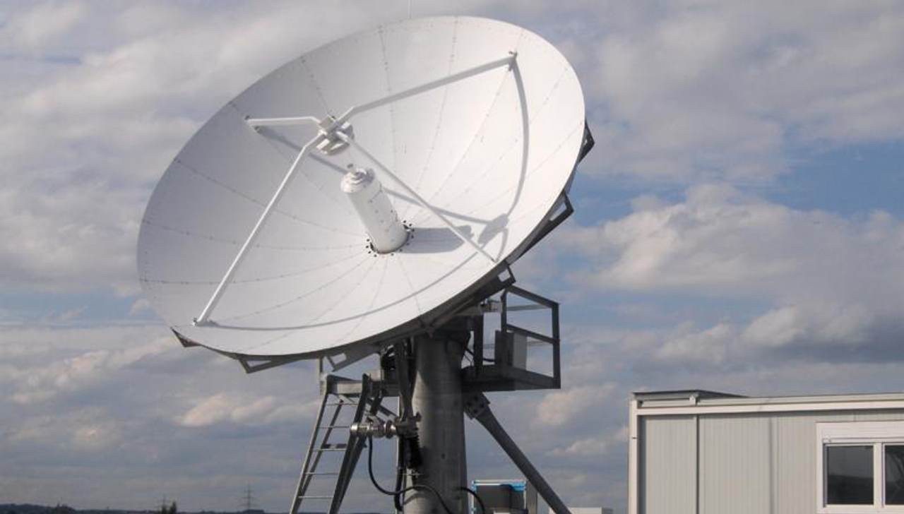
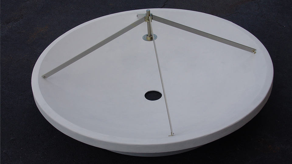
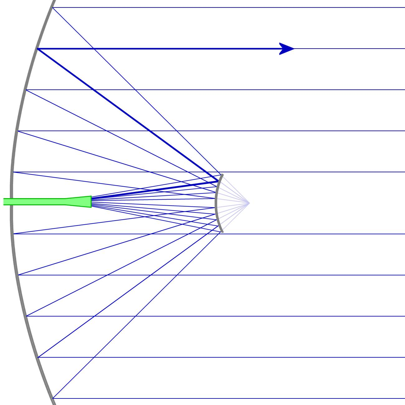
The Cassegrain antenna consists of a primary reflector, a secondary reflector, and a feed. Its core design is inspired by the dual-reflector principle of an optical telescope:The primary reflector utilizes a rotating parabola structure, with its focal point coinciding with the virtual focal point of the secondary reflector. The geometric properties of the parabola ensure that the parallel beam from the secondary reflector forms a uniform phase plane on the aperture plane, resulting in a sharp beam.The sub-reflector is a rotated hyperboloid with one focus coinciding with the focus of the primary reflector and the feed positioned at the other focus. The diffuse reflection properties of the hyperboloid make the spherical waves emitted by the feed, after reflection, appear to be emitted from the focus of the primary reflector, thus achieving beam focusing.The feed system typically utilizes a linearly polarized horn antenna, with a polarization twisting device ensuring that the polarization of the electromagnetic wave matches the receiving system. For example, in satellite communications, after the vertically polarized wave emitted by the feed is reflected by the sub-reflector, the main reflector rotates the beam polarization 90° using a polarization twisting structure, eliminating the effects of obstruction.II. Implementation and Advantages of Linear Polarization Technology(1) Principle of Polarization Twist TechnologyTraditional Cassegrain antennas suffer from increased sidelobe levels and decreased gain due to obstruction caused by the feed, sub-reflector, and support rods. Polarization twisting technology addresses this issue through the following methods:Sub-reflector Design: The sub-reflector is constructed using metal bars parallel to the feed polarization direction. The metal grid strongly reflects vertically polarized waves, while its transmittance for horizontally polarized waves is over 90%.Polarization Conversion: After the vertically polarized wave emitted by the feed source is reflected by the secondary reflector onto the primary reflector, the primary reflector rotates the beam polarization 90° using a polarization twister (such as a dielectric plate or metal grid), resulting in a horizontally polarized wave. At this point, the metal grid transmits horizontally polarized waves, theoretically eliminating the effects of secondary reflector obstruction.(2) Performance Advantages of Linearly Polarized AntennasCompact Structure: The rear-fed design places the feed source behind the primary reflector, shortening the feed line length to less than one-third of that of the forward-fed design, reducing transmission loss and lowering noise. For example, in a 12-meter aperture antenna, the Cassegrain structure reduces the longitudinal dimension by 40%, facilitating large antenna deployment.High Gain and Low Sidelobe: By optimizing the curvature parameters of the primary and secondary reflectors, the aperture field amplitude is high inside and low outside, with uniform phase distribution, resulting in a gain of 30-50 dB and a sidelobe level below -15 dB. For example, a certain Cassegrain antenna achieves a gain of 35 dB in the 26.5-40 GHz band, with a first sidelobe ≤ -18 dB.Flexibility and Scalability: The dual-reflector structure provides seven geometric parameters (primary reflector focal length, aperture diameter, secondary reflector real and virtual focal lengths, vertex-to-focal length, etc.), allowing for on-demand adjustment of beamwidth, pointing accuracy, and other indicators. For example, by modifying the secondary reflector shape to achieve a shaped design, aperture field amplitude uniformity can be improved by 20%.III. Application Scenarios of Cassegrain Linearly Polarized Antennas(1) Satellite Communication Earth StationsLarge and medium-sized earth stations: Cassegrain antennas are widely used in C, Ku, and Ka-band satellite communications due to their high gain and low sidelobe characteristics. For example, the XB-CA42-500 antenna produced by Beijing Xibao Electronic Technology Co., Ltd. achieves a gain of 37dB in the 18.0-26.5GHz frequency band, supporting high-speed data transmission and multi-beam switching.Low-Earth Orbit Satellite Systems: To meet the rapid beam switching requirements of low-Earth Orbit constellations such as Starlink, Cassegrain antennas achieve beam pointing accuracy of ≤0.1° by optimizing feed layout, reflector curvature, and servo feed algorithms.(2) Radio Astronomy ObservationsDeep Space Exploration: Cassegrain antennas, as core components of radio telescopes, support observations in high-frequency bands (such as 236GHz). For example, one antenna model achieves a gain of 50dB in the 203.5-236.5GHz frequency band, with a beamwidth of only 0.4°, enabling the capture of weak cosmic signals.Multi-beam combining: By combining multiple Cassegrain antennas to form an interferometric array, high-resolution imaging is achieved. For example, a radio telescope array consists of 66 Cassegrain antennas, with an equivalent aperture of 100 meters and a resolution of milli-arcseconds.(3) Microwave Relay CommunicationsLong-Distance Transmission: Cassegrain antennas support communications in the EHF band (30-300 GHz). Polarization multiplexing technology enables simultaneous transmission of dual-polarized beams, increasing spectral efficiency by 100%. For example, a microwave relay system using Cassegrain antennas achieves a 10 Gbps transmission rate in the 40 GHz band and a coverage distance of up to 50 kilometers.Anti-Interference Design: Linearly polarized antennas use polarization isolation technology (such as orthogonal polarization beam separation) to reduce the impact of multipath interference. Test data shows that in complex electromagnetic environments, Cassegrain antennas achieve a signal-to-noise ratio 6-8 dB higher than feedforward antennas. IV. Technical Challenges and Development Trends(1) Existing Technical BottlenecksManufacturing Precision Requirements: The reflector surface error must be controlled within λ/50 (λ is the wavelength). Otherwise, gain will be reduced, placing extremely high demands on the processing technology.Thermal Deformation Compensation: Large antennas experience thermal deformation under solar radiation, resulting in beam pointing deviation. For example, the focal length of the main reflector of a 12-meter antenna under sunlight varies by 2mm, requiring real-time correction using a "best-fit hyperboloid" algorithm.(2) Future Development DirectionsIntelligence and Automation: Integrating AI algorithms enables adaptive adjustment of the antenna feed attitude and fault prediction. For example, a new antenna achieves pointing accuracy of 0.05° using a machine learning model.New Material Applications: Carbon fiber composite materials are used to reduce antenna weight (40% lighter than metal structures) while increasing structural rigidity. For example, an 8-meter antenna with a carbon fiber main reflector weighs only 1.2 tons and can withstand a force 12 typhoon.Terahertz frequency band expansion: Research and development of Cassegrain antennas supporting the 0.1-10 THz frequency band to meet the needs of 6G communications and quantum computing. Preliminary tests show that a terahertz antenna achieves a gain of 55 dB and a beamwidth of 0.2° in the 340 GHz band, laying the foundation for future ultra-high-speed communications.With its compact structure, high gain, and low sidelobe advantages, Cassegrain linearly polarized antennas have become core equipment in satellite communications, radio astronomy, and microwave relays. With breakthroughs in polarization twisting technology, shaping design, and the application of new materials, their performance continues to improve. In the future, they will evolve towards intelligence, high frequency bands, and lightweight design, providing key support for the construction of global information networks.


: ≥54dBi First sidelobe level: ≤-28.5dBi")